

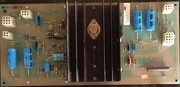
Atari Regulator Audio Board
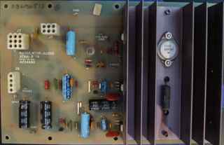
The linear power supply and sound amplifier board for most classic Atari games.
Bitter Experience
This walk through is a product of my experience restoring many Atari classics. I have no formal Electronic Engineer degree. I was in Grade school when these boards were conceived and produced. Everything I have written, photographed and mapped out in tables is the result of evaluating, swapping and repairing these boards. I have burned through almost a hundred 10 ohm 1/4 watt resistors in writing this journal.
Take this as a journal, not a text book. I learned some things from the best: elektronforge.com clarified the purpose of the different circuits on the board with their excellent “Application Guide” page. Bob Roberts sells get well kits and hosts component maps to help you do it yourself.
Hindsight History Lesson
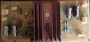
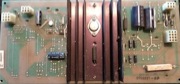
As near as I can tell from tracing backward there was a board called A034485 copyright 1979. This is labeled “REGULATOR/AUDIO” on the boards I have encountered. This board fits the earlier Atari classics like Asteroids. I call it the A/R or A/R-I. This is also called the half board because it has the heat sink and left half of the follow-up A035435 A/R-II board.
The A/R-II had 6 revisions according to all sources. The A/R was also given a revision, -03, which indicates there may have been a -02 that never made it to production.
| Picture (Click for larger image) | Audio Amp | +5V DC | +12V DC | -5V DC | +22V DC | -22V DC |
|---|---|---|---|---|---|---|
 A/R-01 | J8 | J7 5&6 | No | No | No | No |
 A/R-II-01 | J8 | J7 5&6 | No | No | No | No |
 A/R-II-02 | J8 | J7 5&6 | J10 | J10 | J10 | J10 |
 A/R-03 | J8 | J7 5&6 | No | No | No | No |
 A/R-II-03 | J8 | J7 5&6 | J10 | J10 | J10 | J10 |
| A/R-II-04 Never Captured | J8 | J7 5&6 | No | No | J10 | J10 |
| A/R-II-05 Never Captured | J8 | J7 5&6 | No | No | No | No |
 A/R-II-06 | No | J7 5&6 | J10 | J10 | J10 | J10 |
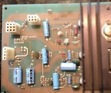
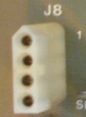
J8 Audio Amplifier
This is the audio (Speaker) amplifier connection. The A/R-01 connector has 4 pins numbered 1 down to 4 as viewed in the photograph below. All the A/R-II version and the A/R-03 have the square connector further down.
A/R-01
 |
|
The board pictured was damaged while moving up a steep stair. Pin 4 snapped at the board. The sound circuit for Channel 1 (SPKR1) was open and the game had no sound.
Note the 1 printed next to the top pin to indicate the number sequence.
A/R-II and A/R-03
|  |
|
The Audio Amplifier seems to include the two large capacitors in series. Most of the boards feature a pair of 3300 μF capacitors. The A/R-01 had 1000 μF capacitors (caps) but by the time the A/R-03 was released they were upgraded to the 3300’s. Most cap kits will have the 3300 in them.
Replacing the 1000’s with the 3300’s is reported to cause distortion in the Asteroids audio. This is preferred to having no sound (the usual reason for replacing the caps or recapping) but if 1000’s can be had, use them in Asteroids. The work of amplifying the audio falls to a pair of TDA2002 transistors marked Q5 and Q7.
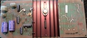
J6 Power Input
This connector is 6 pins and completes a 10.3 VDC circuit. This is the power supplied to the board from the transformer in the bottom of the cabinet. Remove this cable when you are troubleshooting the transformer block. The 10.3 VDC is unregulated according to the manuals. I usually read a high +13 VDC in practice. Readings are usually about +13.6 but never more than +13.8 on my meter.
The table below describes the pin numbers as seen in the photograph above.
| 1 | 2 | 3 |
| 4 | 5 | 6 |
| Pin | 1 | 2 | 3 |
|---|---|---|---|
| Connection | GND* | GND* | +10.3 VDC*** |
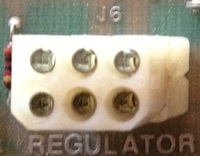 | |||
| Pin | 4 | 5 | 6 |
| Connection | N/A** | N/A** | +10.3 VDC |
**Pins 4 and 5 are not grounded, linked or connected to the board.
***10.3 VDC Unregulated is the notation in the manual, I always get 13.6 VDC on my meter.
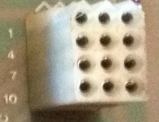
J7 +5 and SENSE
This connector is 9 pins and provides the +5 VDC to the board. The table below describes the pin numbers as seen in the photograph above.
| 1 | 2 | 3 |
| 4 | 5 | 6 |
| 7 | 8 | 9 |
| Pin Connection | 1 GND | 2 SENSE+ | 3 SENSE+ | |||
|---|---|---|---|---|---|---|
| 4 GND | 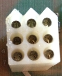 |
| ||||
| Pin Connection | 7 +10.3 VDC | 8 SENSE- | 9 SENSE- | |||
SENSE+ is connected to an LM105H that regulates voltage by comparing it to a return from the main board. The Resistor R29 is the victim if this sense circuit fails. SENSE- is connected to a current limiter that limits current when a ground short is detected. This circuit fries R30 when it fails. The most common cause of failure in both these circuits is a bad edge connection. Check to see if the main board’s pads are good and that the connector is grabbing firmly. A weak clip or bad (worn) pad will cause a failure.
SENSE Mod
When the edge connectors are worn in a machine the owner may elect to modify the SENSE circuits to bypass.
J9 AC Input
J9 is a 6 pin connector. It carries 36V AC to the other half of the board.
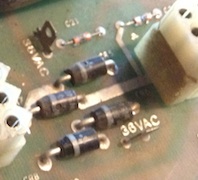
There is a bridge rectifier and test points next to it on the board. This is the source of the +22V DC, -22V DC, +12V DC and -5V DC because they are only present on the board that provide those additional voltages. This is especially evident on the A/R-II-04 which provides only the additional +22 / -22. The bridge rectifier and two 3300 caps are present but the 1μF 50V caps for +12 are missing as are the 22μF 35V caps for -5.
| Pin | 1 | 2 | 3 |
|---|---|---|---|
| Connection | GND* | GND* | 6.3 VAC |
 | |||
| Pin | 4 | 5 | 6 |
| Connection | 36 VAC | 36 VAC | +6.3 VAC |
J10 -5 and 22
| Pin Connection | 1 +22 VDC* | 2 +22 VDC* | 3 -22 VDC* | |||||||
|---|---|---|---|---|---|---|---|---|---|---|
|  |
| ||||||||
| Pin Connection | 10 N/A | 11 GND | 12 GND | |||||||
Cap List
These boards have several components that may need replacement.
A/R-01
Capacitors | |||
|---|---|---|---|
| Qty. | Farad | Volts | Location |
| 2 | 10μf | 25v | 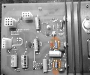 |
| 3 | 470μf | 25v | 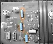 |
| 3 | 1000μf | 25v | 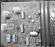 |
Resistors | |||
|---|---|---|---|
| Qty. | Ohm | Watts | Location |
| 2 | 10 ohm | 0.5 W* |  |
* 0.25 Watt was installed at Atari, these will work, but the half watt resistors are preferred replacements
Transistors | |||
|---|---|---|---|
| Qty. | Type | Function | Location |
| 2 | TDA2002 | Audio Amplifier |  |
| 1 | 2N6107 | Voltage Regulator |  |
| 1 | 2N3055 | Voltage Regulator | 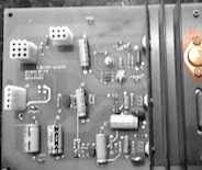 |
A/R-II-01 and A/R-03
Capacitors | |||
|---|---|---|---|
| Qty. | Farad | Volts | Location |
| 3 | 470μf | 25v |  |
| 1 | 1000μf | 25v | 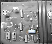 |
| 2 | 3300μf | 35v |  |
Resistors | |||
|---|---|---|---|
| Qty. | Ohm | Watts | Location |
| 2 | 10 ohm | 0.5 W* | 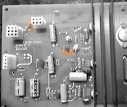 |
* 0.25 Watt was installed at Atari, these will work, but the half watt resistors are preferred replacements
Transistors | |||
|---|---|---|---|
| Qty. | Type | Function | Location |
| 2 | TDA2002 | Audio Amplifier |  |
| 1 | 2N6107 | Voltage Regulator | 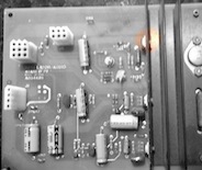 |
| 1 | 2N3055 | Voltage Regulator |  |
A/R-II-02 and -03
Capacitors | |||
|---|---|---|---|
| Qty. | Farad | Volts | Location |
| 3 | 470μf | 25v | 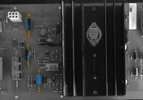 |
| 1 | 1000μf | 25v |  |
| 4 | 3300μf | 35v | 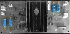 |
| 2 | 1μf | 50v | 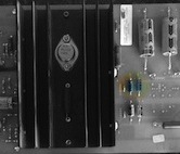 |
| 2 | 22μf | 35v | 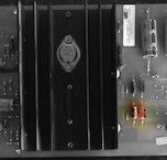 |
Resistors | |||
|---|---|---|---|
| Qty. | Ohm | Watts | Location |
| 2 | 10 ohm | 0.5 W* |  |
* 0.25 Watt was installed at Atari, these will work, but the half watt resistors are preferred replacements
Transistors | |||
|---|---|---|---|
| Qty. | Type | Function | Location |
| 2 | TDA2002 | Audio Amplifier | 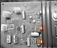 |
| 1 | 2N6107 | Voltage Regulator |  |
| 1 | 2N3055 | Voltage Regulator |  |
| 1 | 7812 | Voltage Regulator | 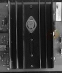 |
| 1 | 7905 | Voltage Regulator | 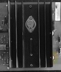 |