

Midway Gun Fight Gun Control
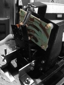
This walk through will focus on the controller PCB for the Aim control on a Midway Gun Fight. The controller PCB has 5 pins.
Pinout
| Pin | Purpose |
|---|---|
| T | Trigger |
| 3 | Gun Down |
| 2 | Extended (Level) |
| 1 | Gun Up |
| C | Common |
Paths
Trigger
The trigger on the pistol grip fires a bullet. Two wire attach to the switch in the pistol grip and to the C and T pins.
Aim
The cowboys can fire in 5 different positions. Pulling the pistol grip toward you will aim the gun up, pushing will lower the angle. Contact is made using 4 brushes and exposed traces on the PCB. The brush attached to Pin C is always in contact. The table indicates Closed when the brush is making contact with the board and closing the circuit with Pin C.
| Pin | Up | - | - | Extend | - | - | Down |
|---|---|---|---|---|---|---|---|
| 1 | Closed | Closed | Closed | Closed | Open | Open | Open |
| 2 | Open | Open | Closed | Closed | Closed | Closed | Open |
| 3 | Open | Closed | Closed | Open | Open | Closed | Closed |
| Video | |||||||
| Binary Value | 1 | 5 | 7 | 3 | 2 | 6 | 4 |
Problem Areas
Brushes and traces eventually wear. Keeping the traces clean and the brushes in contact will be a matter of constant maintenance with this controller.
There are also rubber bumpers that keep the metal of the pistol grip from touching the grounded metal inside the travel path. Not sure if these are electrically sensitive as the switch for the trigger is insulated. It may be there just to protect the pistol grip.
Trigger wires travel up through the pistol grip to the trigger switch. The pistol grip has at least 4 pins center mounted to support the structure and to serve as the axle for the pivot motion and to keep the grip in the control panel. The safety catch and axle can be removed for maintenance. Putting them back in threatens to cut or de-insulate the trigger wires. This was failure point for the unit pictured here.
More Photos: Gun Fight Grip