


Taito Aux(iliary) Power Supply (TAPS)
Link: Full Size Image (1 mB)
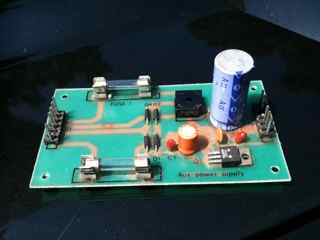
This power converter and conditioner is a straight shot design. J1 is the connector to the AC, the power is converted and conditioned then sent to the J2 DC connector.
J1
Pin 6 is the furthest away in the photograph above, Pin 1 is the closest.
| Pin | Purpose |
|---|---|
| 1 | 11 V Common |
| 2 | Notched for proper plug orientation |
| 3 | 11 VAC |
| 4 | 10 V Common |
| 5 | 10 VAC |
| 6 | Not Used |
J2
Pin 1 is the furthest away in the photograph above, Pin 6 is the closest.
| Pin | Purpose |
|---|---|
| 1 | +13 V |
| 2 | Not Used |
| 3 | Notched for proper plug orientation |
| 4 | GND |
| 5 | GND |
| 6 | -12 V |
Paths
+13 VDC
J1 Pins 4 and 5 pass through the 3A fuse (FUSE 1) and feed the Bridge Rectifier (D5). D5 converts the 10 VAC into +13 and cleans it using the larger C5 electrolytic capacitor. The +13 VDC is supplied on J@ Pin 1 with Ground on Pins 4 and 5.
-12 VDC
J1 Pins 1 and 3 provide 11 VAC to the second Diode Array (bridge rectifier) composed of D1-D4. This circuit uses FUSE 2 (0.5 A) for protection. The triode and remaining 4 capacitors convert the 11 VAC into -12 VDC. This voltage is provided on J2 pin 6 and grounded to Pin 5.
Cap List
Like the popular monitor stories, AR boards have similar capacitors that may need replacement. Most likely you will need to replace only C2 and C5. The tantalum and ceramic capacitors do not have the oiled paper construction and do not dry out over time.
| ID | Farad | Volts | Type |
|---|---|---|---|
| C1 | 10μf | 35V | tantalum |
| C2 | 100μf | 25v | electrolytic |
| C3 | 0.1μf | 32V | ceramic |
| C4 | 10μf | 35V | tantalum |
| C5 | 4700μf | 25V | electrolytic |
More Photos: TAPS