

Wells Gardner K4900
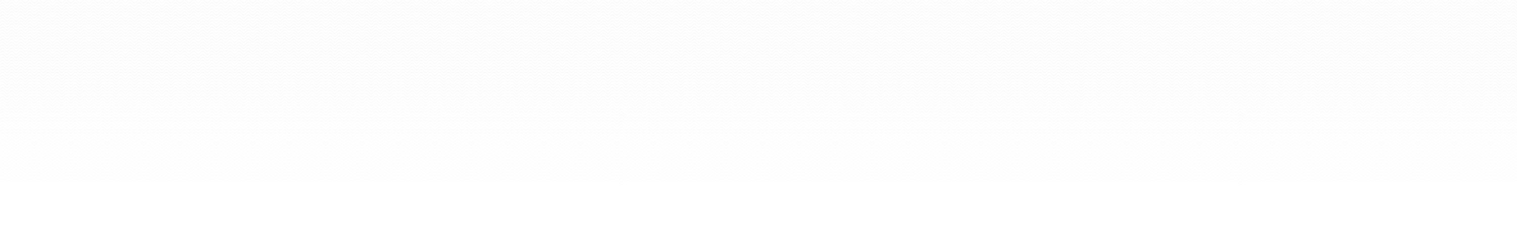
This was a nice compact design from the Wells Gardner folks. They had abandoned the card-type architecture of the 4600’s and squeezed it all in a small chassis.
Soldering Notes
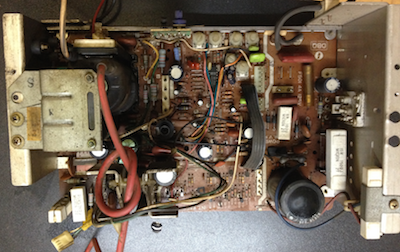
I like to remove components form the solder side of the board. I also like to angle the board to allow gravity to help me work.
When soldering in (adding) components I feed them throughout the holes and then angle the board to allow the solder to run down to the hole instead of dripping on the desk. Removal is the opposite. I am usually pulling lightly on the component while I de-solder. If it is possible to angle the board forward, I do.
Solder Theory
I believe the engineering type that invented hole-through solder boards intended to make this an easy, if manual, process. Each hole has a nice ring of trace (a metal circle around the hole) and ample room for the lead (wire sticking out of the component). The job is simple, drop enough solder on the wire that is fills the hole and touched the trace.
The solder should only stick to the lead and the trace. The green, bare board is supposed to repel solder. If you dump too much solder on the board you may connect to another trace and change the circuit (that is bad).
Cap Kit
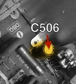
Align the chassis so the adjustment knobs are away from you. That puts the Flyback on the left and the fuse on the right.
Remember high voltage ratings are permitted, lower voltage ratings with likely pop when powered. I like to attack the board right to let (generally) so this list reflects that order.
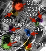
| Number | Cap | Location | Notes |
|---|---|---|---|
| C506 | 22 ㎌ @ 160 V | Right | Yellow above |
| C205 | 470 ㎌ @ 16 V | Center | |
| C352 | 47 ㎌ @ 25 V | Center | |
| C354 | 47 ㎌ @ 25 V | Center | |
| C351 | 1 ㎌ @ 50 V | Center | |
| C201 | 1000 ㎌ @ 25 V | Center | |
| C315 | 1 ㎌ @ 50 V | Center | |
| C303 | 2.2 ㎌ @ 50 V | Center | |
| C301 | 330 ㎌ @ 50 V | Center | |
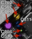
| C313 | 47 ㎌ @ 250 V | Left | |
| C702 | 10 ㎌ @ 160 V | Left | |
| C507 | 47 ㎌ @ 250 V | Left | |
| C311 | 4.7 ㎌ @ 160 V | Left | |
| C308 | 2.2 ㎌ @ 50 V | Left | |
| C310 | 10 ㎌ @ 160 V | Left | |
| C701 | 1000 ㎌ @ 25 V | Left |